I recently got a TFT display and a serial port board with a small bit of breadboard space hooked up to my Raspberry Pi3, for running Pytomation.
See the side menu for more about automation with Pytomation. I wanted something I could power down, removing power from the Pi board, then start up again with the push of a button.
The entire assembly is built with the following components (see the article from January about configuring the TFT display):
 .
.
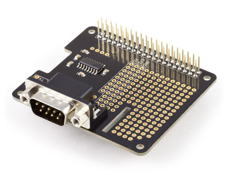
This is the Pi serial expansion board including breadboard area. It is available from https://www.abelectronics.co.uk.
.
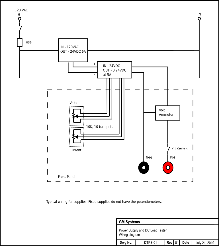
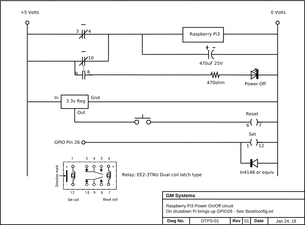
This is the schematic of the power circuit. It works as follows:
Once the Pi has booted pressing the bottom button on the TFT display, which is connected to GPIO 17, will initiate a shutdown of the operating system,
The very last action taken during the shutdown sequence is to enable (logic high, +3.3v) GPIO pin 26. GPIO 26 turns on the "set" coil of the relay which
in turn will remove power from the Pi board. The 470uF capacitor provides just enough additional power to the Pi to properly latch the relay before removing
power. Pressing the pushbutton will pulse the "reset" coil and power will be restored to the Pi, which then boots.
Here is a quick video of the board operating.
Parts list:
- Raspberry Pi3 with USB power supply and SD card, running Raspbian 9.
- Adafruit 2.8" Capacitive display from BC Robotics
- SerialPiPlus an RS232 board with breadboard space.
- 3.3 volt dual coil latching relay model EE2-3TNU.
- 3.3volt three terminal regulator.
- IN4148 diode.
- Green LED.
- 470 ohm, 1/4 or 1/8 watt resister
- Normally open pushbutton switch.
- 470uF, 25volt electrolytic capacitor.
- USB male connector/cable end.
- Various standoffs and hardware.
Once the board is complete with the power on/off circuit you must make some changes to your Raspbian installation.
There are two things that must be done. Add support for the power down button on the TFT display and add support for
GPIO pin 26 to change to a high state (3.3v) one it is safe to remove power from the Pi3.
To get the TFT display working see my article from January 2018,
PiTFT
TFT display button support:
This tells the Pi to watch GPIO pin 27 which is one of the buttons on the TFT display, when
pressed it will shutdown the Pi.
Login and edit the /boot/config.txt file to add the following at the bottom of the file.
dtoverlay=gpio-shutdown,gpio_pin=27
This is from the /boot/overlays/README file.
Name:   gpio-shutdown
Info:   Initiates a shutdown when GPIO pin changes. The given GPIO pin
        is configured as an input key that generates KEY_POWER events.
        This event is handled by systemd-logind by initiating a
        shutdown. Systemd versions older than 225 need an udev rule
        enable listening to the input device:

                ACTION!="REMOVE", SUBSYSTEM=="input", KERNEL=="event*", \
                        SUBSYSTEMS=="platform", DRIVERS=="gpio-keys", \
                        ATTRS{keys}=="116", TAG+="power-switch"

        This overlay only handles shutdown. After shutdown, the system
        can be powered up again by driving GPIO3 low. The default
        configuration uses GPIO3 with a pullup, so if you connect a
        button between GPIO3 and GND (pin 5 and 6 on the 40-pin header),
        you get a shutdown and power-up button.
Load:   dtoverlay=gpio-shutdown,=
Params: gpio_pin                GPIO pin to trigger on (default 3)

        active_low              When this is 1 (active low), a falling
                                edge generates a key down event and a
                                rising edge generates a key up event.
                                When this is 0 (active high), this is
                                reversed. The default is 1 (active low).

        gpio_pull               Desired pull-up/down state (off, down, up)
                                Default is "up".

                                Note that the default pin (GPIO3) has an
                                external pullup.
GPIO pin 26 support:
Login and edit the /boot/config.txt file to add the following at the bottom of the file.
dtoverlay=gpio-poweroff,gpiopin=26
This is from the
/boot/overlays/README file.
Name:   gpio-poweroff
Info:   Drives a GPIO high or low on poweroff (including halt). Enabling this
        overlay will prevent the ability to boot by driving GPIO3 low.
Load:   dtoverlay=gpio-poweroff,=
Params: gpiopin                 GPIO for signalling (default 26)

        active_low              Set if the power control device requires a
                                high->low transition to trigger a power-down.
                                Note that this will require the support of a
                                custom dt-blob.bin to prevent a power-down
                                during the boot process, and that a reboot
                                will also cause the pin to go low.
Now assemble all the pieces. Stack the serialpi board on the Pi first , then the TFT display hat on top of the serial board,
then power on your Pi. You should be able to safely shutdown the Pi by pushing the
bottom button on the TFT display. To turn the Pi back on, press the pushbutton wired into the power circuit.
Here is a picture of the completed project:
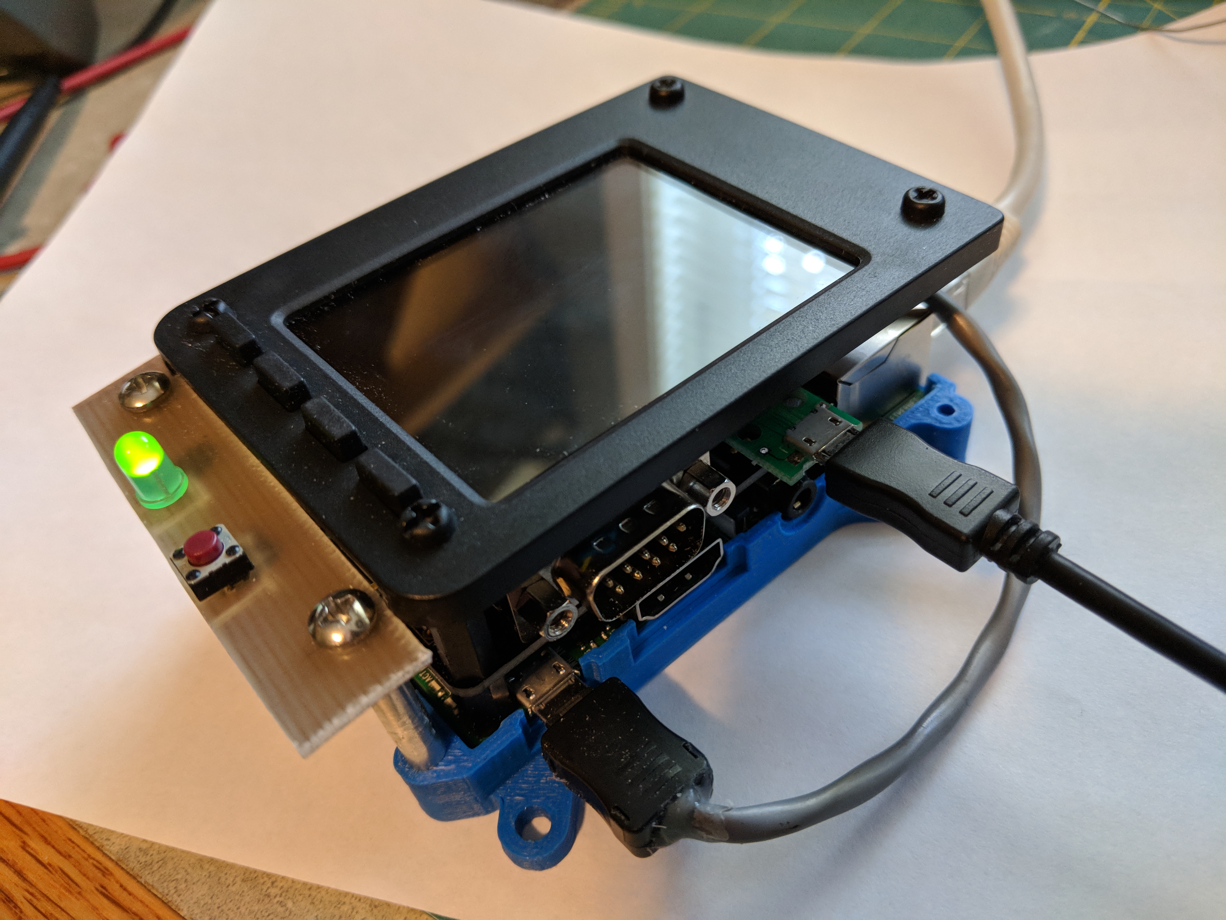
.
 This site is the personal blog and project repository of George Farris.