Laser engraving on a CR-10 3d printer.
Posted on: March 28, 2019, in 3D Printer, All, Laser
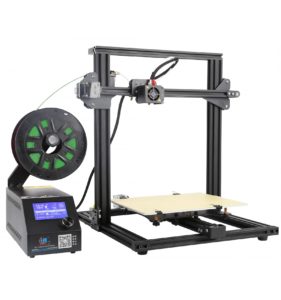
CR-10 3D Printer
A while back I broke down and purchased a 3D printer, I chose the Creality CR-10 Mini. It's bascially the same as a regular CR-10 but not quite as tall and the bed is slightly smaller.
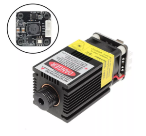
2300mW, 445nm laser
I also purchased a 445nm blue laser module from Banggood to engrave and cut. It is effective in cutting such things as paper, acrylic, cardboard, cloth, plastic and wood up to about 3mm. It will engrave a wide variety of material.
The CR-10 Mini has the following features.
- Print size: 300 x 220 x300mm
- Nozzle Diameter: Standard 0.4mm – can use 0.6mm
- Software: Cura, Slicer3d, Repetier-host
- File format: stl,obj, gcode
- Print speed: Normal 60mm/s, Max 100mm/s
- Filament diameter: 1.75mm
- Filament type: PLA, ABS, PTEG, TPU, WOOD, Nylon, Carbon fiber, Copper, etc
- Power requirements: 120VAC, 250W
Interfacing to the CR-10
The laser has a 4 pin or 3 pin connection depending which version you purchase, both will work. Regardless of which version you get an interface must be built for optimum life of your laser. I have included the interface here:
This connects to the part cooling fan port inside your CR-10.
Mounting on the CR-10
The laser modules normally comes with magnets attached and I printed a laser mount (thanks VE7IT for creating in OpenSCAD) which can be fitted onto the side of the laser and clipped onto the print head for easy attachment and removal.
Here is the OpenSCAD file: cr-10-mini-laser-mount.scad
If your laser does not come with magnets search google for N50 10x3mm magnets with 3mm hole.
I got mine from Bangood. Here is a link to a picture of the magnets.

Caution vision damage possible.
Please use the appropriate glasses to protect your eyes. Make sure they are rated for 445nm wavelength. This laser is seriously powerful and can blind you in an instance.
Software and setup
Once you have your laser interface wired up and connected to the printer, you can start engraving / cutting.
I use the Inkscape Laser Plugin from Jtech Photonics. I will include links to local copies of the software etc at the bottom of the article. There are a few steps to perform when sending gcode to the printer that will make your life much easier.
- Focus your laser.
- Setup G92 offsets.
- Burn grid onto 3mm plywood for reference.
Focus your laser
Home your print head for all three axes. G28 is the gcode to send if you do it manually.
Raise your print head to 100mm about the surface and take note of the distance. Because I use a 9mm piece of plywood I have to raise mine 109mm.
Move the laser out to the center of the bed. On top of the laser is a lower power button, depress the button and turn on the power. It’s a good idea to use your glasses just in case it comes on full power.
You may need to remove you glasses to focus the laser at low power. Turn the focus knob on the laser until you get as small a dot as possible, then turn the power off.
Setup G92 offsets
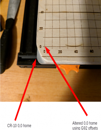
Since the laser sits offset from the print head it will not start at 0,0 of the X, Y coordinates of the CR-10 Mini. We must tell the printer before we run the laser where 0,0 actually is.
What this does is specify an offset so the gcode for the laser can actually be created with 0,0 but the printer will move the head to our offset 0,0. Also if you recall I mentioned to remember the Z or height offset to actually have 100mm above the surface. For my setup I send this to the CR-10 before every laser job.
Steps to find your offsets.
- Home your print head
- With your software, (Octoprint, Repetier-host etc), jog your print head over until it is approximately 1cm in from the edge, on both the X and Y axes.
- Step in 1mm increments and note down how many there are for each axis.
These are the measurements that I have to use.
G28
G92 X-45 Y-27 Z-9
G0 Z100
M300 S1000 P400
G4 P3000
M300 S2000 P200
The M300 command plays a sound through the speaker and G4 P3000 waits 3 seconds.
Note: Change Z to always maintain 100mm above your engraving surface.
Here is an example:
Once you have this setup you can use my Inkscape laser template that shows the grid in a locked layer. You will always know where your engraving will start.
Download this and put it in your Inkscape Templates folder. On my Linux system it is in the
~/.config/inkscape/templates/ folder.
Now open Inkscape and from the menu choose File->New From Template->laser.
 This site is the personal blog and project repository of George Farris.
