Dual band- VHF/UHF dipole
Posted on: November 12, 2020, in All, Ham Radio - SDR
This is a description of a dual band dipole that I built for 145.00MHz and 440MHz. It is a simple build consisting of the following materials:
- 1″ PVC T
- Approx 48″ of 1″ schedule 40 PVC pipe
- 60″ of 3/8″ copper tube
- 8′ RG58 copper coax
- Various mounting hardware and U bolts
- 30 minute epoxy
Test Build
I built a test version first and tested with my antenna analyzer, I made the elements longer than the required frequencies so I could cut them back to actual lengths once the antenna was permanently constructed.
Here are some pictures, test results and notes of my test build.
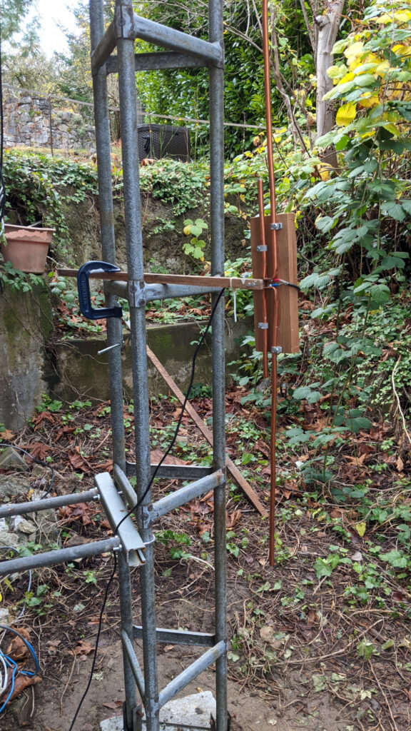
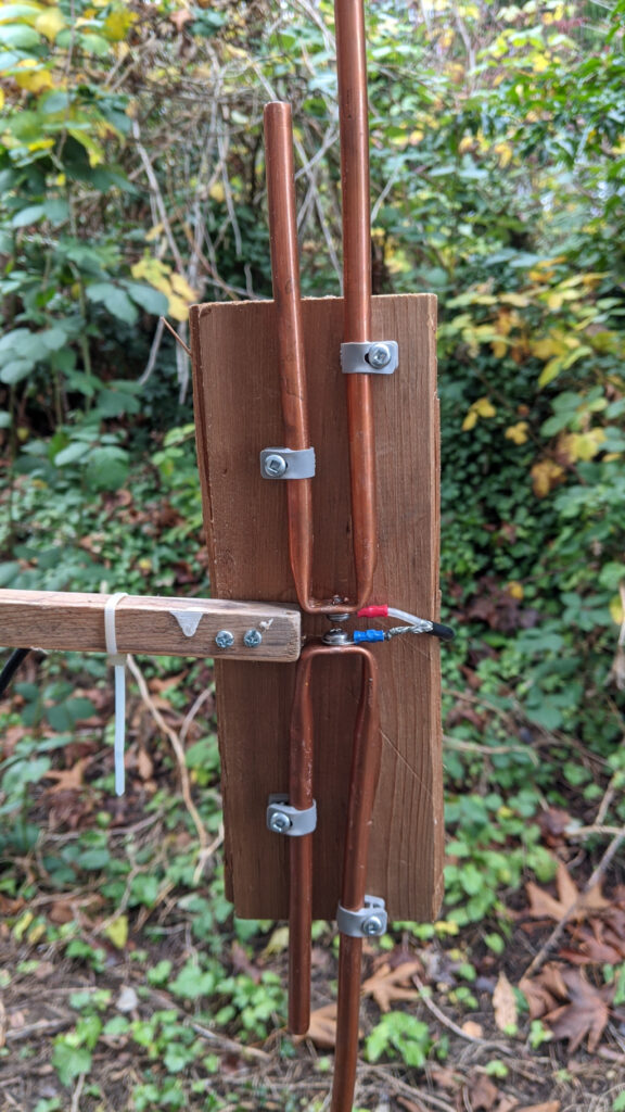
As you can see from the photos above, a test build of the antenna is very simple and easy to construct. The screw terminals on the coax feed point are approximately 3mm apart.
When testing, I calibrated the antenna analyzer with the coax connected to help cancel out any effects of the coax, the coax is approximately 8 feet long. OSL calibration with the EU1KY analyzer consists of 3 measurements on the end of the coax.
- 0 Ohms
- 50 ohms
- Shorted
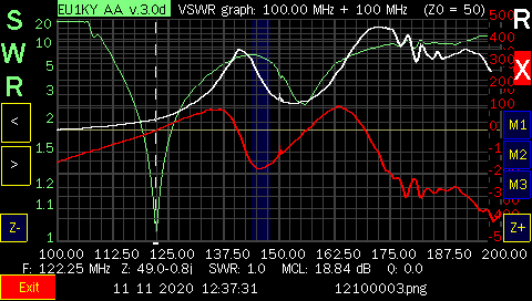
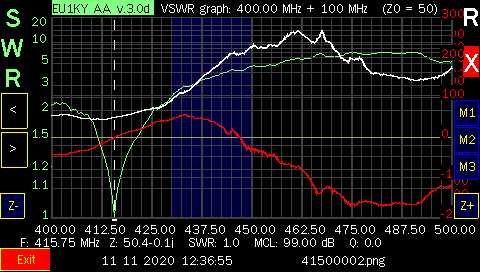
Once this is complete we can now scan our frequency ranges and see the results. I first scanned the antenna from 100MHz to 200MHz and then from 400MHz to 500MHz.
I cut the VHF elements with an approximate length for resonance in around 120MHz to 130MHz, 22″, to ensure they would be longer than required for 145MHz, this allowed me to trim the elements later for exact placement in the Amateur band.
The UHF, elements were also longer at 7″.
Impedance with the dipole is a function of the distance from the metal tower or antenna mast. As you move the antenna closer to the metal structure the impedance drops until theoretically it would be 0 ohms at 0 distance.
I started with the antenna clamped to the tower at a distance of about 16″, this gave me an impedance of 66 Ohms. I moved the antenna closer to the tower until I had an impedance of close to 50ohms on each band.
The results are below and as you can see it works very well for the resonant frequencies of both the VHF and the UHF elements.
The 3/8″ tubing is large enough to provide enough bandwidth to cover both the 144MHz and 44MHz Amateur bands with a low SWR.
Now on to permanent construction and tuning.
Finished Antenna
With the test build confirming the antenna design seems valid I moved on to the finished construction.
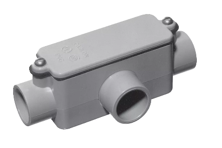
First the elements were mounted inside a 1″ PVC T enclosure. I then 3D printed a spacer to hold the elements in place and poured epoxy in to seal the elements from weather and holds them solidly in place.
You could also make the spacer out of cardboard as it is not structural but used to stop the epoxy from leaking out.
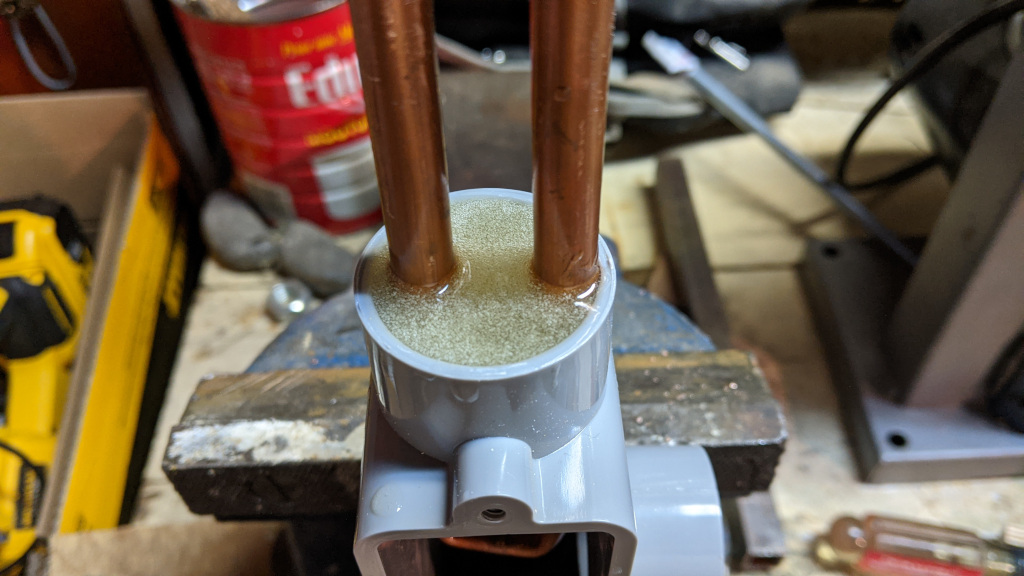
Here is a shot of the epoxy seal for the upward facing elements. I used West Systems epoxy but you could use anything as long as it seals against weather and structurally holds the elements in place.
I sealed the bottom elements in a similar fashion but only used about 3/16 of an inch of epoxy. After the bottom epoxy set, I drilled two small holes, to enable moisture to escape the PVC T enclosure.
I connected coax to the elements as shown in the test build above, mounted the antenna on a 10 foot steel mast in the middle of the driveway and proceded to trim the elements to bring the antenna into the Amateur bands of 145MHz and 440MHz.
 This site is the personal blog and project repository of George Farris.