This site is the personal blog and project repository of George Farris.

If you are looking for the old Cowichan Valley Linux Users Group, check the side navigation. This site contains links to various projects that I either created or contribute to.

You will also find my Github page and Youtube channel here. Contact: cwg@cowlug.org


Latest News

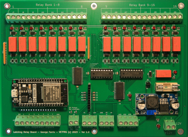
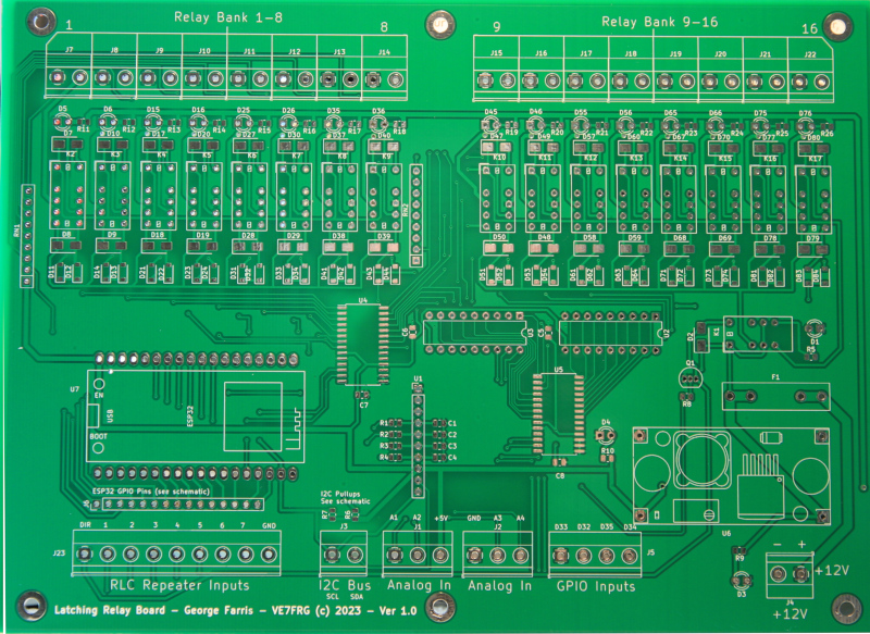
WIFI Latching Relay Board

Posted on: July 27, 2023, in Equipment

ESP32 based latching relay board with digital inputs and optional 16 bit analog inputs.

This board was designed for solar powered, mountain top, radio repeater sites, but is certainly not
limited to that use.

Most relay boards use standard relays that are energised continuously when they are closed and
use anywhere in the range of 30 to 100mA or more. With 10 relays taking say 40mA, on all the time,
plus the board electronics, you are looking at approximately .5A continuous current draw 24/7.
On a solar powered site this may be too much.

In addition, with standard relays, if the power is removed the relays will all drop out removing power from
equipment you may not want to go down. A latching relay board solves these issues with no current
being drawn by coils and static state contacts on power cycle.

https://github.com/horga83/Latching-Relay-Board

Ordering

Bare and pre-built boards may be ordered from me, please email <farrisg at gmsys.com>

Bare boards are US $29.00 plus shipping.
Currently Pre-built board prices are available on a quote basis, due to component prices.
The pre-built board may be ordered with 8 relays to save on cost.
36pin ESP32 modules are available with the bare board as an option.

Features

  • 36pin ESP32 (doit dev v1) microcontroller with watchdog code.
  • 16 latching relays each one with a single usable contact rated at 2A.
  • 7 of the 16 relays are in parallel with sink outputs of a repeater controller such as RLC-4.
  • Low current indicator LEDS for all relays.
  • 4 Inputs for door switch alarms or other uses.
  • 4 Analog I/O points available by including optional ADS1115 board.
  • Remaining pins on ESP32 brought out to header for use.
  • I2C bus brought out to terminal blocks.
  • Operates on 12VDC at approx 60mA.
  • Communication is by WIFI.
  • Python test and “relay” application.

Commands

The table below outlines the ASCII command sequences the board accepts.

Note: All commands must be terminated with a ‘\n’ character.

CommandDescription
STGet status (returns status of all 16 relays)
See note below about status
RCnnClose relay nn – example RC00 or RC12
ROnnOpen relay nn
RTnnToggle relay nn
OAOpen all relays
CLClose all relays
TETest all relays – close all then open
A0Get Analog A0 value
A1Get Analog A1 value
A2Get Analog A2 value
A3Get Analog A3 value
I1Get input I1 state – GPIO33
I2Get input I2 state – GPIO32
I3Get input I3 state – GPIO35
I4Get input I4 state – GPIO34


DC Power Supply and Load Tester

Posted on: July 17, 2019, in AllEquipmentSmall Touch Displays

This post describes my build of a new power supply and DC load tester for testing batteries and power supplies.  Kudos go to Lawrence Glaister, VE7IT who is also building one and was instrumental in the co-design of this project.

Features:

  • Dual adjustable supplies 0-24VDC at 5amps.
  • 12VDC Fixed at 5 amps.
  • 5VDC Fixed at 5 amps.
  • Dual USB power ports.
  • DC Load tester up to 20 amps (see note).
  • All supplies are isolated and change be chained together.
  • Load testor showsdisplays Time, Volts, Current and mAh.
  • Load can run for user supplied time or voltage set point.

Missing Features to be added:

  • Filter board for DC conditioning.
  • Logging of Load test for input into spreadsheet etc.

Description:

I built this supply in and old rack mount case but it could be built into anything.  Power supplies are off the shelf from our friends in China. 

The DC Load was a custom build and all schematics and code for microcontroller is available from my github page.  I will include links here as well.  Schematics are drawn in Kicad.  If you haven’t tried Kicad you should, it’s amazing and 100% freely available open source code.  I use it under Linux.

Power supplies:
The four power supplies are split into two fixed and two variable supplies, each capable of sourcing 5 amps. The two fixed supplies are set at 12 and 5 VDC.  The variable ones can realistically run from 1 volt up to 24.
 
Typical wiring for one panel is shown here:

I bought all my supplies from Banggood but I'm sure they can be had from anywhere.

The 120VAC to 24VDC supply is a: "Geekcreit® 4A To 6A 24V Switching Power Supply Board AC-DC Power Module"

The other supplies for the variable and fixed side are constant current, constant voltage supplies, where the on board potentiometers were replaced with panel mounted potentiometers. I soldered 3 pin headers to the supplies for easy mounting and replacement.


The 5VDC fixed supply is also connected to two USB A connectors on the front panel for powering and charging purposes. They run through the ammeter as well.

The wiring for the USB includes resistors that allow full current charging of supported devices.


Microscope

Posted on: March 21, 2016, in AllEquipment

Just picked up one of these microscopes for surface mount work.

Features:
  • High quality optical glass elements
  • High definition erect stereo images over a wide field view
  • 2 levels of total magnifications: 10X and 20X
  • Extremely long working distance allows enough operation space
  • 45°inclined binocular head
  • Low heat LED light - harmless for touching
  • Additional flexible lamp holder provided for different lighting angles
  • Ocular tube has diopter adjustment
  • Adjustable inter-pupillary distance to fit anyone's eyes
  • Sturdy small metal boom stand
  • Product GS and CE approved
  • Manufacturer in business 30+ years

Specifications:
  • Model: G22C
  • Head: 45°Inclined binocular.
  • Eyepieces: wide field WF10X/20 and WF20X/10
  • Objective: 1x
  • Total magnification: 10x & 20x
  • Ocular tube has diopter adjustment ±5dp
  • Interpupillary distance: 2-3/16" ~ 2-15/16"(55~75mm)
  • Working distance: 9 " (230mm)
  • Maximum field of view: 3/4" (20mm)
  • Focus adjustment stroke: 1-3/4" (43mm)
  • LED illumination
  • Power supply: 110V/60Hz (US and Canada)
  • Dimension: 18" x 5-1/8" x 15" (46cm x 13cm x 38cm)
  • Net weight: 14 lb 12oz ( 6.7kg)
  • Shipping weight: 17 lb (8kg)