This site is the personal blog and project repository of George Farris.

If you are looking for the old Cowichan Valley Linux Users Group, check the side navigation. This site contains links to various projects that I either created or contribute to.

You will also find my Github page and Youtube channel here. Contact: cwg@cowlug.org


Latest News

PR-3000-FS-N01 Wind speed transmitter

Posted on: November 8, 2021, in AllPythonRaspberry Pi

This describes getting a FS-N01 anemometer working with some python 3 code on a Raspberry PI with a Waveshare 2 channel RS485 hat.
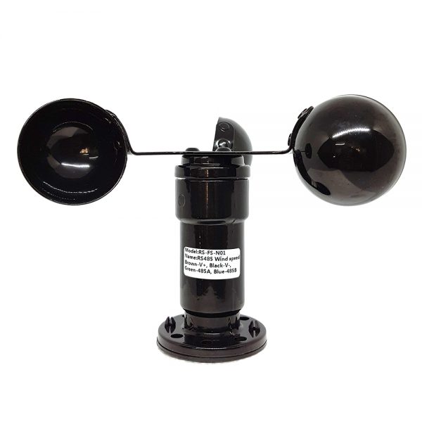
FS-N01 Wind Speed Transmitter
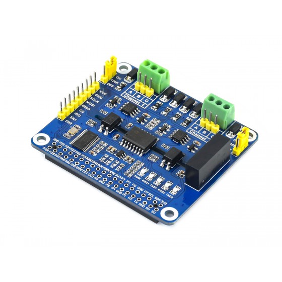
Waveshare 2 Channel RS485 HAT

The anemometer has Chinese markings on it for V+, V-, 485A and 485B.  Obviously the V+ and V- are for power supply and I used 12VDC.  The manual I found online states 10-30VDC.

The RS485 lines are marked with a Chinese symbol for their colour.  My manual stated Yellow and blue and yet the device I have was Green and Blue.  Just lookup the corresponding Chinese character and get the translation for the colour if you don’t speak the language.  Mine was:

 
V+ – Brown – 棕
V- – Black – 黑
485A – Green – 绿
485B – Blue – 绿

The Waveshare 2 channel RS485 hat required an edit to the /boot/config.txt file of the raspberry pi. Add the following line and then reboot.

dtoverlay=sc16is752-spi1,int_pin=24

You should now see 2 devices in /dev:

/dev/ttySC0 and /dev/ttySC1, these of course are your serial ports.


Copy the python3 code below and your wind speed should be displayed in Kilometers per hour when you run it.


#!/usr/bin/python3
# -*- coding:utf-8 -*-
# Copyright (C) 2021  George Farris <farrisg@gmsys.com>
#
# This program is free software: you can redistribute it and/or modify
# it under the terms of the GNU General Public License as published by
# the Free Software Foundation, either version 3 of the License, or
# (at your option) any later version.

# This program is distributed in the hope that it will be useful,
# but WITHOUT ANY WARRANTY; without even the implied warranty of
# MERCHANTABILITY or FITNESS FOR A PARTICULAR PURPOSE.  See the
# GNU General Public License for more details.

# You should have received a copy of the GNU General Public License
# along with this program.  If not, see <http://www.gnu.org/licenses/>.

# Anemometer.py is reference code to read a PR-3000-FS-N01, RS465 Anemometer
# on a raspberry pi 4 using a Waveshare 2 channel RS485 HAT.
# https://www.waveshare.com/2-ch-rs485-hat.htm

import serial
import os
import sys
import time
import RPi.GPIO as GPIO

SERIAL_PORT = "/dev/ttySC0"
TXDEN_1 = 27
TXDEN_2 = 22

# Calculate CRC16 Checksum
def _crc16(data, no):
    crc = 0xffff
    poly = 0xa001   # Polynomial used for Modbus RS485 applications
    temp = no

    while True:
        crc ^= data[temp - no]        
        for i in range(0, 8):
            if crc & 0x0001:
                crc = (crc>>1) ^ poly
            else:
                crc >>= 1
        no -= 1;
        if no == 0:
            break

    return crc & 0xffff

# Open the serial port at 4800 buad
ser = serial.Serial(port=SERIAL_PORT, baudrate=4800)

# Set the mode on the Raspberry Pi GPIO
GPIO.setmode(GPIO.BCM)
# Set this to avoid warning of channel in use
GPIO.setwarnings(False)

# Set the GPIO pin as output for port 1 and 2 on the WAVESHARE RS485 HAT (SC16IS752)
# and then set the bit HIGH to enable the ports
GPIO.setup(TXDEN_1, GPIO.OUT)
GPIO.setup(TXDEN_2, GPIO.OUT)
GPIO.output(TXDEN_1, GPIO.HIGH)
GPIO.output(TXDEN_2, GPIO.HIGH)

# Now lets setup and inquiry packaet for the PR-3000-FS-N01, RS485 Anemometer

# Set the length of the transmit buffer
tx_buf = [0] * 8
tx_buf[0] = 1    # MODBUS ID
tx_buf[1] = 3    # MODBUS Function code (read holding register)
tx_buf[2] = 0    # Starting address of register - High byte
tx_buf[3] = 0    # Low byte
tx_buf[4] = 0    # How many registers to read - High byte
tx_buf[5] = 1    # Low byte

# Get the CRC of the packet
crc = _crc16(bytearray(tx_buf), 6)
# Add the crc bytes to the end of the transmit buffer
tx_buf[6] = (crc & 0x00ff)
tx_buf[7] = ((crc >> 8) & 0xff)

# pack the buffer
data = bytearray(tx_buf)

# Set board in transmit mode and write data
GPIO.output(TXDEN_1, GPIO.LOW)
ser.write(data)
# Waiting to finish sending
time.sleep(0.01)
# Set board to receive mode
GPIO.output(TXDEN_1, GPIO.HIGH)

# get six bytes plus crc = 8 bytes total
data_t = [0] * 8
for i in range(7):
    data_t[i] = int.from_bytes(ser.read(1), 'little')

# Current wind speed example: 0056 H (hexadecimal) = 86 => Winds = 8.6m / s
# Add bytes 3 and 4 then divide by 10 to get meters per second
# Then divide by 1000 to get Kilometers per second
# now mutitply by 3600 to get kmh
ms = float(data_t[3] + data_t[4]) / 10.0
kmh = ms / 1000 * 3600
print('Kilometers per hour {0:>.1f}'.format(kmh))

# Typical response example
#b'\x01'
#b'\x03'
#b'\x02'
#b'\x00'
#b'\x56' Current wind speed: 0056 H (hexadecimal) = 86 => Winds = 8.6m / s
#b'\xb8'
#b'D'


Dual band- VHF/UHF dipole

Posted on: November 12, 2020, in AllHam Radio - SDR

This is a description of a dual band dipole that I built for 145.00MHz and 440MHz.  It is a simple build consisting of the following materials:

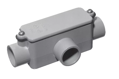
  • 1″ PVC T
  • Approx 48″ of 1″ schedule 40 PVC pipe
  • 60″ of 3/8″ copper tube
  • 8′ RG58 copper coax
  • Various mounting hardware and U bolts
  • 30 minute epoxy

Test Build

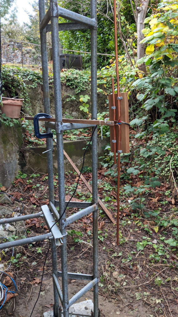
I built a test version first and tested with my antenna analyzer,  I made the elements longer than the required frequencies so I could cut them back to actual lengths once the antenna was permanently constructed.

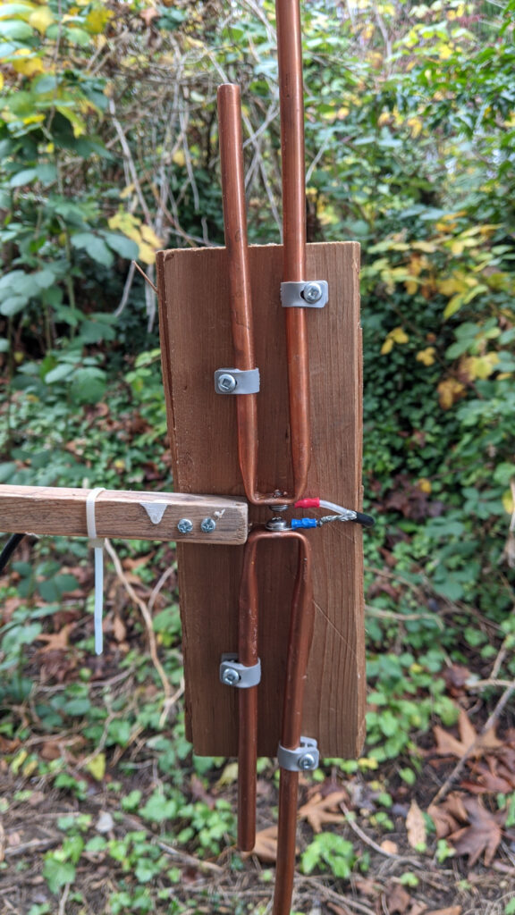
Here are some pictures, test results and notes of my test build.


As you can see from the photos above, a test build of the antenna is very simple and easy to construct.  The screw terminals on the coax feed point are approximately 3mm apart.

When testing, I calibrated the antenna analyzer with the coax connected to help cancel out any effects of the coax,  the coax is approximately 8 feet long.  OSL calibration with the EU1KY analyzer consists of 3 measurements on the end of the coax.

  1. 0 Ohms
  2. 50 ohms
  3. Shorted

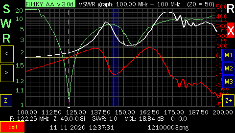
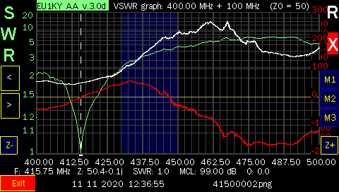
Once this is complete we can now scan our frequency ranges and see the results.  I first scanned the antenna from 100MHz to 200MHz and then from 400MHz to 500MHz. 

I cut the VHF elements with an approximate length for resonance in around 120MHz to 130MHz, 22″, to ensure they would be longer than required for 145MHz, this allowed me to trim the elements later for exact placement in the Amateur band.

The UHF, elements were also longer at 7″.

Impedance with the dipole is a function of the distance from the metal tower or antenna mast.  As you move the antenna closer to the metal structure the impedance drops until theoretically it would be 0 ohms at 0 distance.

I started with the antenna clamped to the tower at a distance of about 16″, this gave me an impedance of 66 Ohms.  I moved the antenna closer to the tower until I had an impedance of close to 50ohms on each band.

The results are below and as you can see it works very well for the resonant frequencies of both the VHF and the UHF elements.

The 3/8″ tubing is large enough to provide enough bandwidth to cover both the 144MHz and 44MHz Amateur bands with a low SWR. 

Now on to permanent construction and tuning.


Finished Antenna

With the test build confirming the antenna design seems valid I moved on to the finished construction.

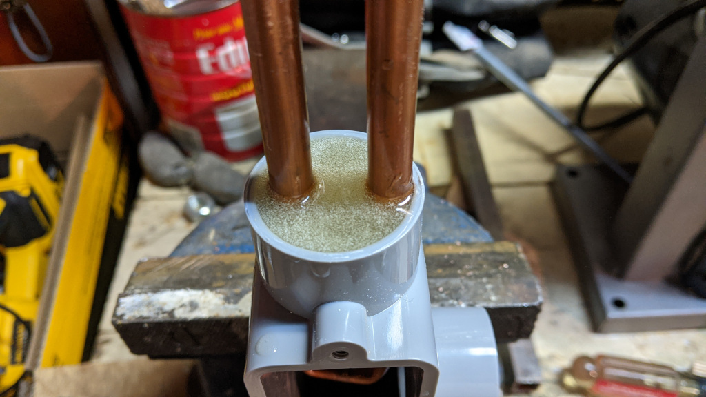
First the elements were mounted inside a 1″ PVC T enclosure.  I then 3D printed a spacer to hold the elements in place and poured epoxy in to seal the elements from weather and holds them solidly in place.

You could also make the spacer out of cardboard as it is not structural but used to stop the epoxy from leaking out.

Here is a shot of the epoxy seal for the upward facing elements.  I used West Systems epoxy but you could use anything as long as it seals against weather and structurally holds the elements in place.

I sealed the bottom elements in a similar fashion but only used about 3/16 of an inch of epoxy.  After the bottom epoxy set, I drilled two small holes, to enable moisture to escape the PVC T enclosure.


I connected coax to the elements as shown in the test build above, mounted the antenna on a 10 foot steel mast in the middle of the driveway and proceded to trim the elements to bring the antenna into the Amateur bands of 145MHz and 440MHz.


EU1KY Antenna Analyzer

Posted on: October 23, 2020, in AllHam Radio - SDR

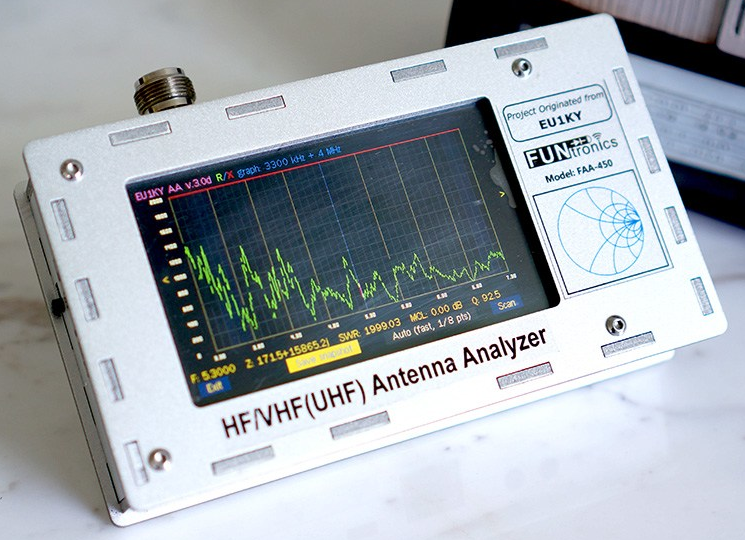
This page is a description of the modifications made to the EU1KY antenna analyzer project.

The FAA-450 Antenna Analyzer is an open source project built from STM32-F7 Discovery board. It has the following features:
  • Colour TFT LCD with capacitive touch.
  • HF/VHF(UHF) frequency coverage (500KHz-500MHz.
  • Built-in TDR function.
  • Multiple scanning curves including SWR.

The analyzer uses DSP technology to analyze the sampled signal and derive the their magnitude ratio and phase difference.

Full open source software is available at bitbucket.org/kuchura/eu1ky_aa_v3.

Development is done by cross compiling for the STM32F746 board on windows (Embitz IDE) or linux (makefile with arm-none-eabi-gcc). The generated F7Discovery.hex file found in the bin/Release folder is uploaded to the device using ST-Link loader.

Programming with Windows
ST-Link loader is available from STMicroelectronics. You will need to get the STSW-LINK004 utility and STSW-LINK007 packages.

Programming with Linux
Install stlink with your package manager.
Connect a mini usb cable to the left most (ST-LINK) port, this port is also used for charging and serial port remote control.

Goto the bin/Release folder and issue this command:

"st-flash --format ihex write F7Discovery.hex"
or
"st-flash write F7Discovery.bin 0x8000000"


The right most USB port labeled USB-HS is used to access the SD card when the "USB HSReader" main menu option has been selected.


List of Custom Software Modifications

Modify splash screen to display QSL card.

TDR chart
Splash screen


To replace the splash screen, create a BMP or a PNG file exactly 480x272 pixels in size. BMP's should be 24 bits. Copy it to the SD card in the AA folder.

See the software changes below.

Modify the signal generator screen.
The analyzer can function as a continuous wave signal generator over a frequency range of 500kHz to 599MHz. Signals above 200MHz are actually using the 3rd harmonic of the internal source.

Generator Screen
Reformated Signal Generator screen

The signal levels are low (0.1 to 0.2vpp), but do radiate when attached to an antenna!. Using the generator mode and a frequency counter, one can adjust the internal crystal calibration factor to get the generator accurate within a PPM or so.

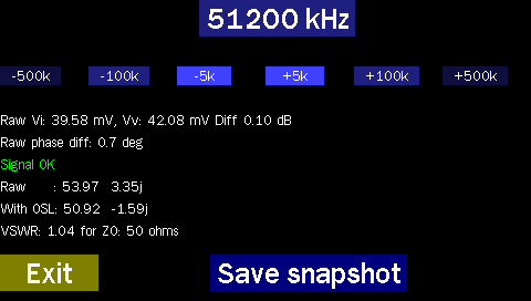
Tapping on the frequency display opens an onscreen keypad where a new frequency in kHz may be entered. Steps of plus and minus 500kHz, 100kHz or 5kHz may be activated by pressing the onscreen row of 6 keys under the frequency display.
Several lines of diagnostic information are displayed that can be used to troubleshoot the hardware receivers, the OSL calibration and the VSWR calculation code. One can also perform a screen save to aid in debugging.

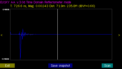
Modify the TDR screen to display coax length in metric and imperial units.

TDR chart
TDR scan showing both metric and imperial lengths

Modify the highlighted ham bands to represent the North American frequency ranges available.
See panvswr2.c for reference.

On the CONFIGURATION screen of your analyzer, hit Next_param until you see SHOW_HIDDEN, set it to YES. Now find the parameter labeled IARU Region and set appropriately. In North America we are Region 2.
Also, you can modify the SWR panoramic display to position the cursor bar on the point of lowest SWR on the displayed graph, if you like.

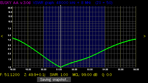
SWR chart
SWR scan of 6M vertical

Software Modifications

Modify the Src/main.c file on approximatley line 122, add the while statement.
#ifndef _DEBUG_UART
if (ShowLogo()==-1)// no logo.bmp or logo.png file found:
    LCD_DrawBitmap(LCD_MakePoint(90, 24), logo_bmp, logo_bmp_size);// show original logo
    while(!TOUCH_IsPressed());      // lpg hang until screen tapped
#endif
on approximately line 138 of Src/main.c change
Sleep(1000);
to
Sleep(100);

To force version timestamp because the windows script doesnt work with wine when running under linux.
Modify the Src/analyzer/window/mainwin.c file on approximately line 472, after the line below, add the the two #defines, remember to change the callsign.

//Initialize textbox context
TEXTBOX_InitContext(&main_ctx);

//modified by KD8CEC
#define BUILD_TIMESTAMP_US "23-Oct-2020-VE7FRG"
#define BUILD_TIMESTAMP_D "2020-10-23-VE7FRG"

if (DatumDDMMYYYY)
    
To display cable length in m and ft in a different screen location,
change Src/analyzer/window/tdr.c on approximately line 239
tdr.c  display cable length in m and ft in a different screen location
    FONT_Print(FONT_FRANBIG, TextColor, BackGrColor, 220, 200, "%.2fm %.1fft", lenm,lenm * 3.2808);    
    

Files / Downloads / Links

Free windows IDE for ARM: https://www.embitz.org/.
STMicroelectronics ST-Link software: https://www.st.com/en/development-tools/st-link-v2.html.

A new version based on the KD8CEC mods
Adds S21, 1200Mhz+, beeper, rtc, FT8 and much more).

Oct 23 2020 hex image: F7Discovery.hex - 1.7M analyzer image.
Oct 23 2020 source files: Analyzer_EU1KY_CEC_AKF-Oct-23-2020.zip.

Github repository for above image https://github.com/ve7it/Analyzer_EU1KY_CEC_AKF

Github repository forked from https://github.com/ted051/Analyzer_EU1KY_CEC_AKF

Linsmith related links

You can download John Coppens ON6JC/LW3HAZ excellent Linsmith program from
http://jcoppens.com/soft/linsmith/index.en.php

VE7IT's linsmith remote control patch: linsmith-remote.patch for linsmith-0.99.28 (19.2kB).


Older project source files

Oldest project source files: eu1ky_aa_v3-16-aug-2018.zip (8.1Mb).
Another version project source files: eu1ky_aa_v3-6-sept-2018.zip (9.0Mb).
Modified project source files: eu1ky_aa_v3.zip (10.0Mb).

Supplier

Analyzer kit/assembled supplier: www.elekitsorparts.com

Setting up a new STMF746G-DISCO CPU board

I had the unfortunate opportunity to drop my analyzer, I really don't recommend doing that. Needless to say it did not survive. The CPU board was damaged and the display no longer worked. I ordered a new board from Mouser.

The battery charging would not work until I upgraded the firmware on the board, Use the LINK-007 package mentioned above to upgrade the firmware, it runs under both Windows and Linux.

On the stock board, you also need to change 4 jumper settings. Change the jumpers as follows: Remove the jumpers from SB3 and SB5, jumper SB1 and SB4. Check SB1 and SB4 for continuity and that SB3 and SB5 are now open circuit. These jumpers are near the SD card connector and are used to drive the Si5351 SCL/SCD on the RF board.


DC Power Supply and Load Tester

Posted on: July 17, 2019, in AllEquipmentSmall Touch Displays

This post describes my build of a new power supply and DC load tester for testing batteries and power supplies.  Kudos go to Lawrence Glaister, VE7IT who is also building one and was instrumental in the co-design of this project.

Features:

  • Dual adjustable supplies 0-24VDC at 5amps.
  • 12VDC Fixed at 5 amps.
  • 5VDC Fixed at 5 amps.
  • Dual USB power ports.
  • DC Load tester up to 20 amps (see note).
  • All supplies are isolated and change be chained together.
  • Load testor showsdisplays Time, Volts, Current and mAh.
  • Load can run for user supplied time or voltage set point.

Missing Features to be added:

  • Filter board for DC conditioning.
  • Logging of Load test for input into spreadsheet etc.

Description:

I built this supply in and old rack mount case but it could be built into anything.  Power supplies are off the shelf from our friends in China. 

The DC Load was a custom build and all schematics and code for microcontroller is available from my github page.  I will include links here as well.  Schematics are drawn in Kicad.  If you haven’t tried Kicad you should, it’s amazing and 100% freely available open source code.  I use it under Linux.

Power supplies:
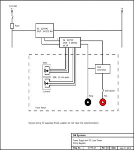
The four power supplies are split into two fixed and two variable supplies, each capable of sourcing 5 amps. The two fixed supplies are set at 12 and 5 VDC.  The variable ones can realistically run from 1 volt up to 24.
 
Typical wiring for one panel is shown here:

I bought all my supplies from Banggood but I'm sure they can be had from anywhere.

The 120VAC to 24VDC supply is a: "Geekcreit® 4A To 6A 24V Switching Power Supply Board AC-DC Power Module"

The other supplies for the variable and fixed side are constant current, constant voltage supplies, where the on board potentiometers were replaced with panel mounted potentiometers. I soldered 3 pin headers to the supplies for easy mounting and replacement.


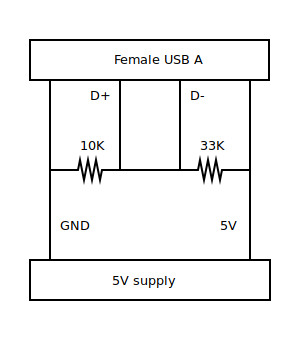
The 5VDC fixed supply is also connected to two USB A connectors on the front panel for powering and charging purposes. They run through the ammeter as well.

The wiring for the USB includes resistors that allow full current charging of supported devices.


Laser engraving on a CR-10 3d printer.

Posted on: March 28, 2019, in 3D PrinterAllLaser

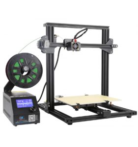
CR-10 3D Printer

A while back I broke down and purchased a 3D printer, I chose the Creality CR-10 Mini. It's bascially the same as a regular CR-10 but not quite as tall and the bed is slightly smaller.

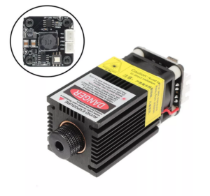
2300mW, 445nm laser

I also purchased a 445nm blue laser module from Banggood to engrave and cut. It is effective in cutting such things as paper, acrylic, cardboard, cloth, plastic and wood up to about 3mm. It will engrave a wide variety of material.

The CR-10 Mini has the following features.

  • Print size:  300 x 220 x300mm
  • Nozzle Diameter: Standard 0.4mm – can use 0.6mm
  • Software: Cura, Slicer3d, Repetier-host
  • File format: stl,obj, gcode
  • Print speed: Normal 60mm/s, Max 100mm/s
  • Filament diameter: 1.75mm
  • Filament type: PLA, ABS, PTEG, TPU, WOOD, Nylon, Carbon fiber, Copper, etc
  • Power requirements: 120VAC, 250W

Interfacing to the CR-10

The laser has a 4 pin or 3 pin connection depending which version you purchase, both will work.  Regardless of which version you get an interface must be built for optimum life of your laser.  I have included the interface here:

CR-10 to Laser Interface

This connects to the part cooling fan port inside your CR-10. 

Mounting on the CR-10

The laser modules normally comes with magnets attached and I printed a laser mount (thanks VE7IT for creating in OpenSCAD) which can be fitted onto the side of the laser  and clipped onto the print head for easy attachment and removal.

Here is the OpenSCAD file: cr-10-mini-laser-mount.scad

If your laser does not come with magnets search google for N50 10x3mm magnets with 3mm hole.

I got mine from Bangood.  Here is a link to a picture of the magnets.

Caution vision damage possible.

Please use the appropriate glasses to protect your eyes. Make sure they are rated for 445nm wavelength. This laser is seriously powerful and can blind you in an instance.

Software and setup

Once you have your laser interface wired up and connected to the printer,  you can start engraving / cutting.

I use the Inkscape Laser Plugin from Jtech Photonics.  I will include links to local copies of the software etc at the bottom of the article. There are a few steps to perform when sending gcode to the printer that will make your life much easier.

  1. Focus your laser.
  2. Setup G92 offsets.
  3. Burn grid onto 3mm plywood for reference.

Focus your laser

Home your print head for all three axes.  G28 is the gcode to send if you do it manually.

Raise your print head to 100mm about the surface and take note of the distance.  Because I use a 9mm piece of plywood I have to raise mine 109mm.

Move the laser out to the center of the bed.  On top of the laser is a lower power button, depress the button and turn on the power.  It’s a good idea to use your glasses just in case it comes on full power.

You may need to remove you glasses to focus the laser at low power.  Turn the focus knob on the laser until you get as small a dot as possible, then turn the power off.

Setup G92 offsets

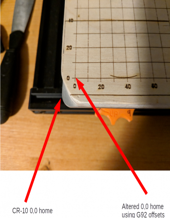
Since the laser sits offset from the print head it will not start at 0,0 of the X, Y coordinates of the CR-10 Mini.  We must tell the printer before we run the laser where 0,0 actually is.

What this does is specify an offset so the gcode for the laser can actually be created with 0,0 but the printer will move the head to our offset 0,0.  Also if you recall I mentioned to remember the Z or height offset to actually have 100mm above the surface.  For my setup I send this to the CR-10 before every laser job.

Steps to find your offsets.

  • Home your print head
  • With your software, (Octoprint, Repetier-host etc), jog your print head over until it is approximately 1cm in from the edge, on both the X and Y axes.
  • Step in 1mm increments and note down how many there are for each axis.

These are the measurements that I have to use.

G28
G92 X-45 Y-27 Z-9
G0 Z100
M300 S1000 P400
G4 P3000
M300 S2000 P200

The M300 command plays a sound through the speaker and G4 P3000 waits 3 seconds.

Note: Change Z to always maintain 100mm above your engraving surface.

Here is an example:

Once you have this setup you can use my Inkscape laser template that shows the grid in a locked layer.  You will always know where your engraving will start.

Inkscape Laser Grid Template

Download this and put it in your Inkscape Templates folder.  On my Linux system it is in the

~/.config/inkscape/templates/ folder. 

Now open Inkscape and from the menu choose File->New From Template->laser.


Home Assistant component development

Posted on: November 14, 2018, in AllHome AssitantPython

This is my attempt to document the development of a component and binary_sensor platform, for the Home Assistant project.

This is the code you should use to meet requirements to get accepted into HA.
Read the article.


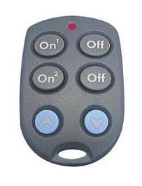
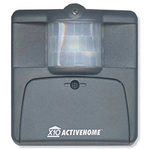
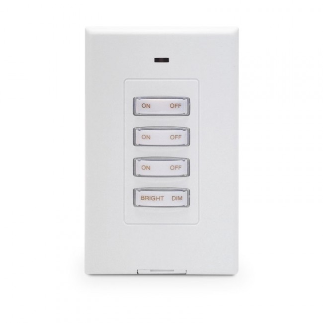
Python driver for the W800rf32 family of X10 RF receivers.

Posted on: October 25, 2018, in AllHome AssitantPython

I recently put a driver up on PYPI for the W800rf32 family of X10 RF receivers from WGL & Associates.
I use this with the following devices:

KR19A
MS16A
RSS13

Here is the github page: W800RF32

This is available to install via PIP:
pip3 install pyW800rf32

All of the logic for the decoding I wrote for the Pytomation project.
Here is an example of using the code, note: very little error checking here.
My reason for doing a PYPI project was to write and include a driver for Home Assistant.


QRP Labs LimeSDR Enclosure.

Posted on: March 27, 2018, in AllHam Radio - SDR

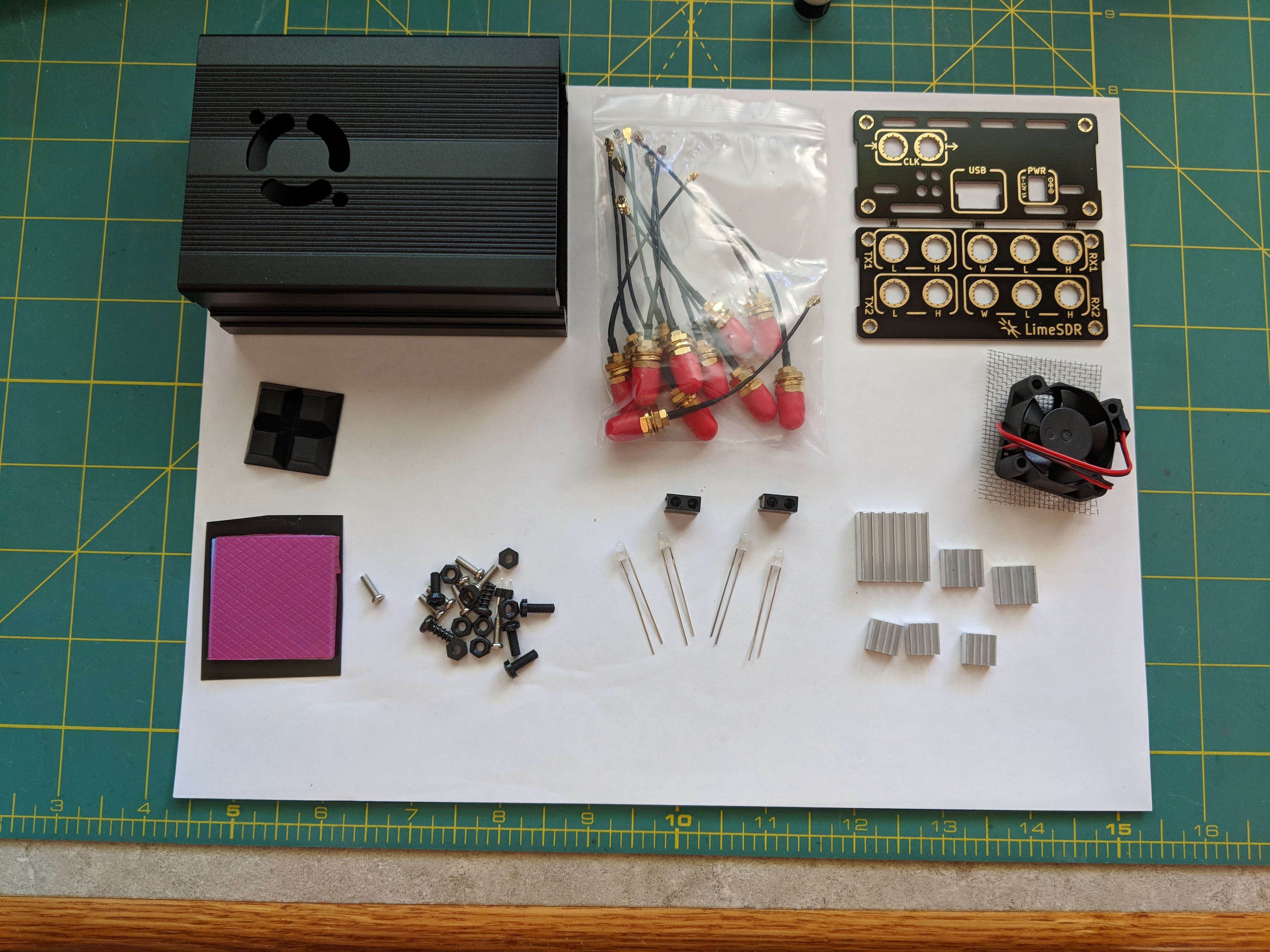
I recently got a LimeSDR board and also bought a QRP Labs case for it. The QRP Labs case brings all the RF connectors out to the front and rear panels and also includes heatsinks for the chips and a case fan.
Assembly instructions are here.

.
Parts list:
    1. 12pcs SMA to U.FL pigtails
    2. aluminium shell bottom (4 holes)
    3. aluminium shell top (fan cutout, 2 holes)
    4. 4 rubber pads
    5. 4 plastic screws
    6. 8 plastic nuts
    7. fan 30x30 5v with mesh
    8. pinheader
    9. heatpad (1pcs, cut later into more pcs)
    10. 6pcs heatsinks (1x + 2x + 3x)
    11. PCB panel (front, rear)
    12. 8 panel screws
    13. 4 bicolor LEDs
    14. 2 LED holders

Software: There are four software packages that I use with the LimeSDR as well as the LimeSuite from Myraid RF.

Users especially Hams should consider the HF mod https://wiki.myriadrf.org/LimeSDR_HF_Performance


Pytomation running on Pi3 with TFT display and power circuit.

Posted on: March 12, 2018, in AllPytomationRaspberry PiSmall Touch Displays

I recently got a TFT display and a serial port board with a small bit of breadboard space hooked up to my Raspberry Pi3, for running Pytomation. See the side menu for more about automation with Pytomation. I wanted something I could power down, removing power from the Pi board, then start up again with the push of a button. The entire assembly is built with the following components (see the article from January about configuring the TFT display):

.

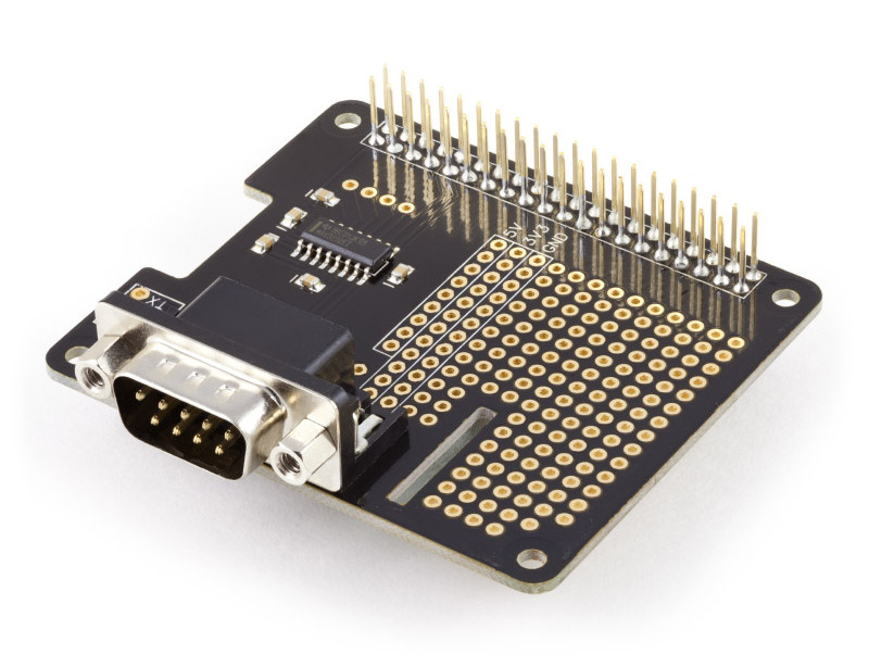
This is the Pi serial expansion board including breadboard area. It is available from https://www.abelectronics.co.uk.


.

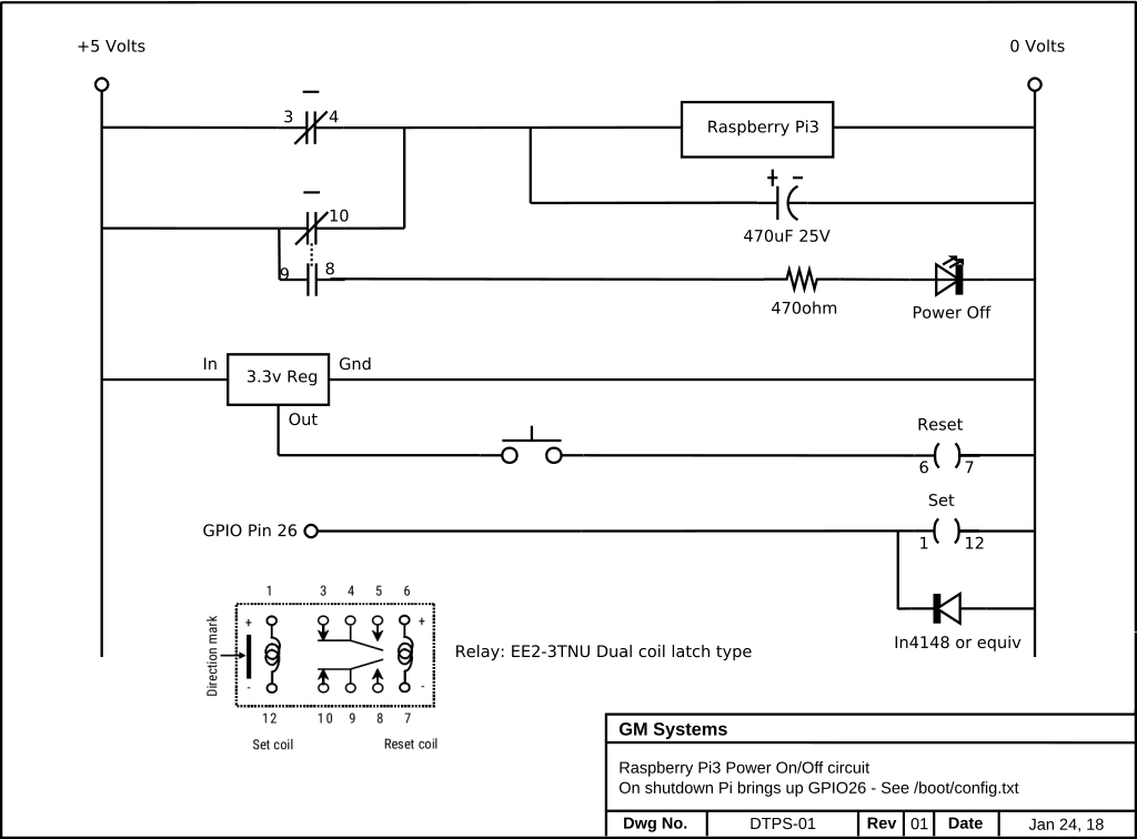
This is the schematic of the power circuit. It works as follows:

Once the Pi has booted pressing the bottom button on the TFT display, which is connected to GPIO 17, will initiate a shutdown of the operating system, The very last action taken during the shutdown sequence is to enable (logic high, +3.3v) GPIO pin 26. GPIO 26 turns on the "set" coil of the relay which in turn will remove power from the Pi board. The 470uF capacitor provides just enough additional power to the Pi to properly latch the relay before removing power. Pressing the pushbutton will pulse the "reset" coil and power will be restored to the Pi, which then boots.

Here is a quick video of the board operating.

Parts list:
    1. Raspberry Pi3 with USB power supply and SD card, running Raspbian 9.
    2. Adafruit 2.8" Capacitive display from BC Robotics
    3. SerialPiPlus an RS232 board with breadboard space.
    4. 3.3 volt dual coil latching relay model EE2-3TNU.
    5. 3.3volt three terminal regulator.
    6. IN4148 diode.
    7. Green LED.
    8. 470 ohm, 1/4 or 1/8 watt resister
    9. Normally open pushbutton switch.
    10. 470uF, 25volt electrolytic capacitor.
    11. USB male connector/cable end.
    12. Various standoffs and hardware.

Once the board is complete with the power on/off circuit you must make some changes to your Raspbian installation. There are two things that must be done. Add support for the power down button on the TFT display and add support for GPIO pin 26 to change to a high state (3.3v) one it is safe to remove power from the Pi3.

To get the TFT display working see my article from January 2018, PiTFT

TFT display button support:
This tells the Pi to watch GPIO pin 27 which is one of the buttons on the TFT display, when pressed it will shutdown the Pi.
Login and edit the /boot/config.txt file to add the following at the bottom of the file.
dtoverlay=gpio-shutdown,gpio_pin=27

This is from the /boot/overlays/README file.

Name:   gpio-shutdown
Info:   Initiates a shutdown when GPIO pin changes. The given GPIO pin
        is configured as an input key that generates KEY_POWER events.
        This event is handled by systemd-logind by initiating a
        shutdown. Systemd versions older than 225 need an udev rule
        enable listening to the input device:

                ACTION!="REMOVE", SUBSYSTEM=="input", KERNEL=="event*", \
                        SUBSYSTEMS=="platform", DRIVERS=="gpio-keys", \
                        ATTRS{keys}=="116", TAG+="power-switch"

        This overlay only handles shutdown. After shutdown, the system
        can be powered up again by driving GPIO3 low. The default
        configuration uses GPIO3 with a pullup, so if you connect a
        button between GPIO3 and GND (pin 5 and 6 on the 40-pin header),
        you get a shutdown and power-up button.
Load:   dtoverlay=gpio-shutdown,=
Params: gpio_pin                GPIO pin to trigger on (default 3)

        active_low              When this is 1 (active low), a falling
                                edge generates a key down event and a
                                rising edge generates a key up event.
                                When this is 0 (active high), this is
                                reversed. The default is 1 (active low).

        gpio_pull               Desired pull-up/down state (off, down, up)
                                Default is "up".

                                Note that the default pin (GPIO3) has an
                                external pullup.


GPIO pin 26 support:
Login and edit the /boot/config.txt file to add the following at the bottom of the file.
dtoverlay=gpio-poweroff,gpiopin=26

This is from the /boot/overlays/README file.
Name:   gpio-poweroff
Info:   Drives a GPIO high or low on poweroff (including halt). Enabling this
        overlay will prevent the ability to boot by driving GPIO3 low.
Load:   dtoverlay=gpio-poweroff,=
Params: gpiopin                 GPIO for signalling (default 26)

        active_low              Set if the power control device requires a
                                high->low transition to trigger a power-down.
                                Note that this will require the support of a
                                custom dt-blob.bin to prevent a power-down
                                during the boot process, and that a reboot
                                will also cause the pin to go low.

Now assemble all the pieces. Stack the serialpi board on the Pi first , then the TFT display hat on top of the serial board, then power on your Pi. You should be able to safely shutdown the Pi by pushing the bottom button on the TFT display. To turn the Pi back on, press the pushbutton wired into the power circuit.

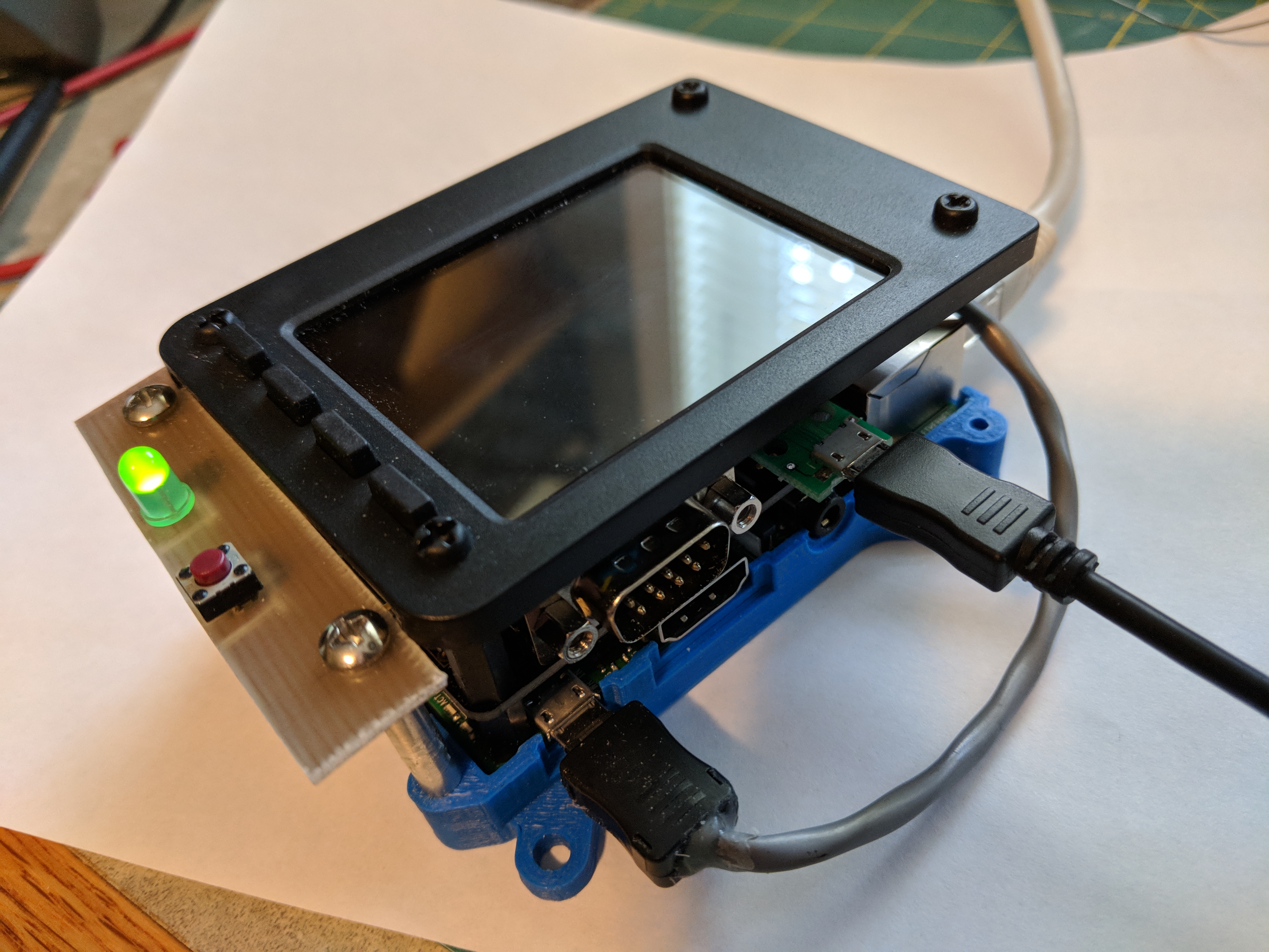
Here is a picture of the completed project:
.


PiTFT small displays for Raspberry Pi

Posted on: January 2, 2018, in AllRaspberry PiSmall Touch Displays

This explains what I had to do to get the Adafruit 2.8″ Capacitive display working under Debian Stretch on a Raspberry Pi 3.

At this point in time, January 2018, the tutorial on the Adafruit page only deals with getting the displays working under Debian Jessie. Stretch was released on June 17th, 2017 and it’s a bit sad that Adafruit has not updated their tutorial.

Here are the steps:

  1. Install Debian Stretch on your Pi3. I used the 2017-08-17 image from downloads.raspberrypi.org.
  2. Make sure everything is up to date with: sudo apt-get update and then sudo apt-get upgrade, then reboot.
  3. Download the adafruit-piftf-helper2.sh script from here, I have a local version here but it may be old now, please check.
  4. Make the script executable -> chmod +x adafruit-pitft-helper2.sh
  5. Now run the script with the sudo command -> sudo ./adafruit-pitft-helper2.sh
  6. and answer the questions
  7.