 This site is the personal blog and project repository of George Farris.
If you are looking for the old Cowichan Valley Linux Users Group, check the side navigation. This site contains links to various projects that I either created or contribute to.
You will also find my Github page and Youtube channel here. Contact: cwg@cowlug.org
Latest News
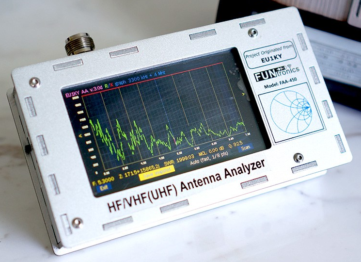
EU1KY Antenna Analyzer
Posted on: October 23, 2020, in All, Ham Radio - SDR
 This page is a description of the modifications made to the EU1KY antenna analyzer project.
The FAA-450 Antenna Analyzer is an open source project built from STM32-F7 Discovery board. It has the following features:
- Colour TFT LCD with capacitive touch.
- HF/VHF(UHF) frequency coverage (500KHz-500MHz.
- Built-in TDR function.
- Multiple scanning curves including SWR.
The analyzer uses DSP technology to analyze the sampled signal and derive the their magnitude ratio and phase difference.
Full open source software is available at
bitbucket.org/kuchura/eu1ky_aa_v3.
Development is done by cross compiling for the STM32F746 board on windows (Embitz IDE) or
linux (makefile with arm-none-eabi-gcc). The generated F7Discovery.hex file found in the bin/Release folder is uploaded to the
device using ST-Link loader.
Programming with Windows
ST-Link loader is available from STMicroelectronics.
You will need to get the STSW-LINK004 utility and STSW-LINK007 packages.
Programming with Linux
Install stlink with your package manager.
Connect a mini usb cable to the left most (ST-LINK) port, this port is also used for charging and serial port remote control.
Goto the bin/Release folder and issue this command:
"st-flash --format ihex write F7Discovery.hex"or
"st-flash write F7Discovery.bin 0x8000000"
The right most USB port labeled USB-HS is used to access the SD card when the "USB HSReader" main menu option has been selected.
List of Custom Software Modifications
Modify splash screen to display QSL card.
![]()
Splash screen
To replace the splash screen, create a BMP or a PNG file exactly 480x272 pixels in size. BMP's should be 24 bits. Copy it to the SD card in the AA folder.
See the software changes below.
Modify the signal generator screen.
The analyzer can function as a continuous wave signal generator over a frequency range
of 500kHz to 599MHz. Signals above 200MHz are actually using the 3rd harmonic of the internal source.
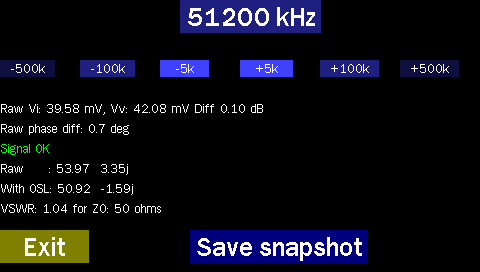
Reformated Signal Generator screen
Tapping on the frequency display opens an onscreen keypad where a new frequency in kHz may be entered. Steps of plus and minus 500kHz, 100kHz or 5kHz may be activated by pressing the onscreen row of 6 keys under the frequency display.
Several lines of diagnostic information are displayed that can be used to troubleshoot the hardware receivers, the OSL calibration and the VSWR calculation code. One can also perform a screen save to aid in debugging.
Modify the TDR screen to display coax length in metric and imperial units.
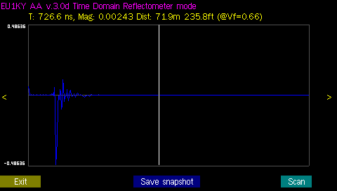
TDR scan showing both metric and imperial lengths
Modify the highlighted ham bands to represent the North American frequency ranges available.
See panvswr2.c for reference.
On the CONFIGURATION screen of your analyzer, hit Next_param until you see SHOW_HIDDEN, set it to YES. Now find the parameter labeled IARU Region and set appropriately. In North America we are Region 2.
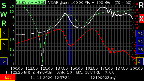
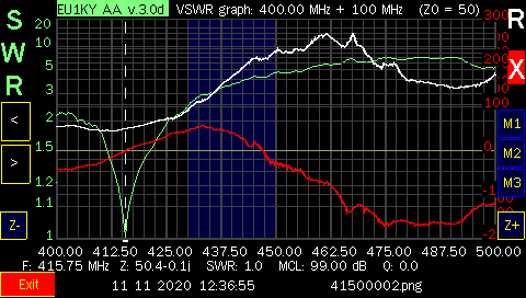
Also, you can modify the SWR panoramic display to position the cursor bar on the point of lowest SWR on the displayed graph, if you like.
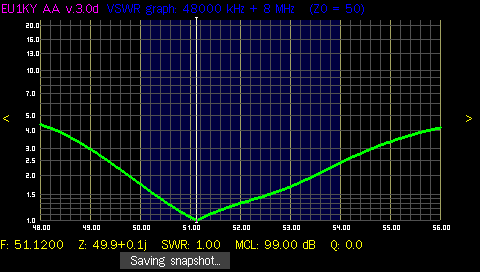
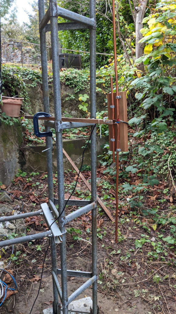
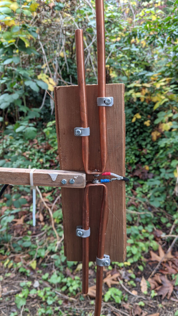
SWR scan of 6M vertical
Software Modifications
Modify the Src/main.c file on approximatley line 122, add the while statement.
#ifndef _DEBUG_UART
if (ShowLogo()==-1)// no logo.bmp or logo.png file found:
    LCD_DrawBitmap(LCD_MakePoint(90, 24), logo_bmp, logo_bmp_size);// show original logo
    while(!TOUCH_IsPressed());      // lpg hang until screen tapped
#endif
on approximately line 138 of Src/main.c change
Sleep(1000);to
Sleep(100);
To force version timestamp because the windows script doesnt work with wine when running under linux.
Modify the Src/analyzer/window/mainwin.c file on approximately line 472, after the line below, add the the two #defines, remember to change the callsign.
//Initialize textbox context
TEXTBOX_InitContext(&main_ctx);

//modified by KD8CEC
#define BUILD_TIMESTAMP_US "23-Oct-2020-VE7FRG"
#define BUILD_TIMESTAMP_D "2020-10-23-VE7FRG"

if (DatumDDMMYYYY)
To display cable length in m and ft in a different screen location,change Src/analyzer/window/tdr.c on approximately line 239
tdr.c  display cable length in m and ft in a different screen location
    FONT_Print(FONT_FRANBIG, TextColor, BackGrColor, 220, 200, "%.2fm %.1fft", lenm,lenm * 3.2808);
Files / Downloads / Links
Free windows IDE for ARM: https://www.embitz.org/.STMicroelectronics ST-Link software: https://www.st.com/en/development-tools/st-link-v2.html.
A new version based on the KD8CEC mods
Adds S21, 1200Mhz+, beeper, rtc, FT8 and much more).
Oct 23 2020 hex image: F7Discovery.hex - 1.7M analyzer image.
Oct 23 2020 source files: Analyzer_EU1KY_CEC_AKF-Oct-23-2020.zip.
Github repository for above image https://github.com/ve7it/Analyzer_EU1KY_CEC_AKF
Github repository forked from https://github.com/ted051/Analyzer_EU1KY_CEC_AKF
Linsmith related links
You can download John Coppens ON6JC/LW3HAZ excellent Linsmith program from
http://jcoppens.com/soft/linsmith/index.en.php
VE7IT's linsmith remote control patch: linsmith-remote.patch for linsmith-0.99.28 (19.2kB).
Older project source files
Oldest project source files: eu1ky_aa_v3-16-aug-2018.zip (8.1Mb).
Another version project source files: eu1ky_aa_v3-6-sept-2018.zip (9.0Mb).
Modified project source files: eu1ky_aa_v3.zip (10.0Mb).
Supplier
Analyzer kit/assembled supplier: www.elekitsorparts.com
Setting up a new STMF746G-DISCO CPU board
I had the unfortunate opportunity to drop my analyzer, I really don't recommend doing that. Needless to say it did not survive. The CPU board was damaged and the display no longer worked.
I ordered a new board from Mouser.
The battery charging would not work until I upgraded the firmware on the board, Use the LINK-007 package mentioned above to upgrade the firmware, it runs under both Windows and Linux.
On the stock board, you also need to change 4 jumper settings. Change the jumpers as follows: Remove the jumpers from SB3 and SB5, jumper SB1 and SB4. Check SB1 and SB4 for continuity and that SB3 and SB5 are now open circuit. These jumpers are near the SD card connector and are used to drive the Si5351 SCL/SCD on the RF board.
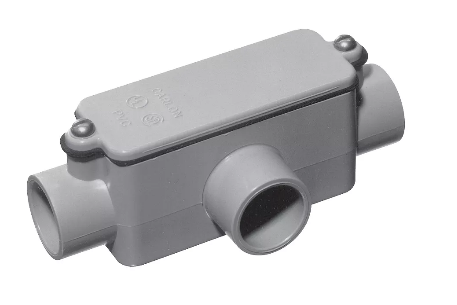
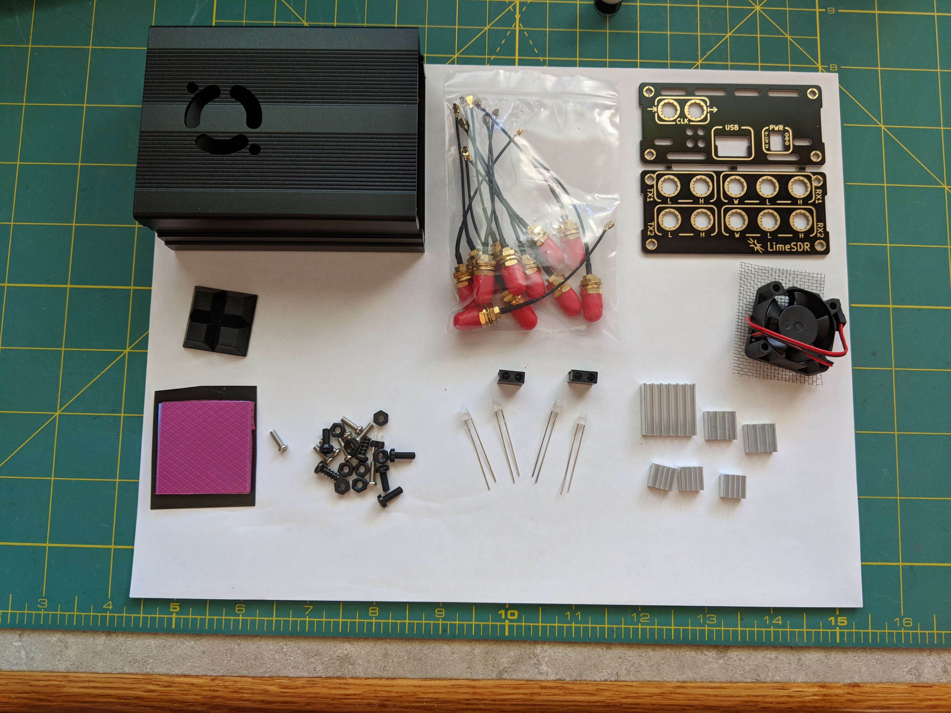
QRP Labs LimeSDR Enclosure.
Posted on: March 27, 2018, in All, Ham Radio - SDR
Assembly instructions are here.
 .
.
Parts list:
- 12pcs SMA to U.FL pigtails
- aluminium shell bottom (4 holes)
- aluminium shell top (fan cutout, 2 holes)
- 4 rubber pads
- 4 plastic screws
- 8 plastic nuts
- fan 30x30 5v with mesh
- pinheader
- heatpad (1pcs, cut later into more pcs)
- 6pcs heatsinks (1x + 2x + 3x)
- PCB panel (front, rear)
- 8 panel screws
- 4 bicolor LEDs
- 2 LED holders
Software: There are four software packages that I use with the LimeSDR as well as the LimeSuite from Myraid RF.
Users especially Hams should consider the HF mod https://wiki.myriadrf.org/LimeSDR_HF_Performance